- Email:info@tsv-valve.com


 Apr 29,2026
An electric gate valve is a vertical‑lift assembly consisting of five core parts: valve body, gate plate, valve stem, valve seat, and electric actuator. The rated pressure and temperature from the nameplate come from the weakest component among these five.
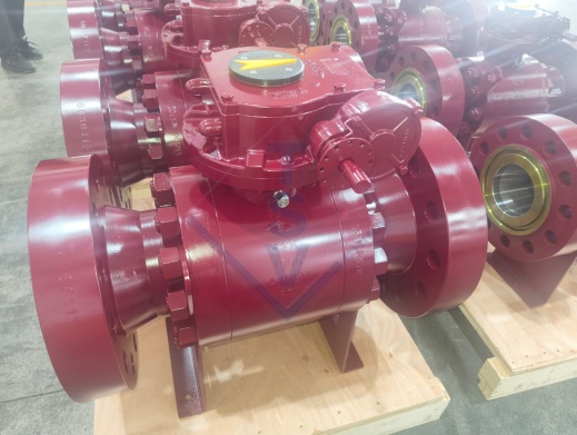
Small‑caliber gate valves (DN200 and below) use integral casting—a single‑piece body that handles pressure more uniformly. Large‑caliber valves (DN500 and above) often use split construction, where left and right bodies bolt together. A split design is easier to manufacture and repair but introduces additional flange seals that become leak paths.
For cast steel gate valves, the body material grades define the pressure‑temperature envelope. WCB (carbon steel) is standard for temperatures up to 425°C. WC6 (1.25% chrome) extends to 540°C. WC9 (2.25% chrome) reaches 570°C. A valve body that cannot handle your actual operating temperature may not catastrophically fail but will begin to distort, pulling the valve seats out of alignment and creating internal leakage where the gate no longer contacts the seats evenly.
Gate valves use either wedge geometry (typical for high‑pressure hard sealing) or parallel geometry (common in low‑pressure soft sealing). Wedge gates incorporate a small angle (typically 3°‑5°) between the sealing surfaces. That taper performs two functions: it forces the gate against both seats during closure, and it compensates for thermal expansion of the valve body.
A parallel gate valve at 550°C will lose seal if the body grows more than the gate, because the surfaces stay parallel and can separate. A wedge gate valve at the same temperature maintains contact because the taper converts body growth into tighter seat contact. This is why power plants and refineries almost exclusively use wedge gate valves for high‑temperature steam isolation services.
An actuator for gate valves must convert motor rotation into linear stem movement through a multi‑turn gear train. The standard arrangement uses an acme or trapezoidal thread on the stem. The actuator's output torque requirement depends on stem thrust, which is itself a function of differential pressure across the gate and stem thread efficiency.
| Valve Parameter | Impact on Actuator Torque |
|---|---|
| Differential pressure across closed gate | Higher pressure = higher thrust to unseat gate |
| Stem thread friction coefficient | Greased stainless steel (μ≈0.15) vs dry carbon steel (μ≈0.30) — torque doubles |
| Gate and seat surface condition | Corroded or scale‑coated surfaces increase seating torque by 50‑100% |
| Temperature effect on lubricant | Standard grease degrades above 120°C — recalculate torque for high‑temp service |
An undersized electric actuator will stall before fully seating the gate. The valve will pass leakage at the seats, the operator will see a “not fully closed” signal, and they will manually override—often damaging the gear train in the process. Field data suggests that approximately 25% of electric actuator service calls trace to inadequate breakaway torque calculation, not actuator failure.
Electric multi‑turn actuators use both position switches (to indicate open/closed) and torque limit switches (to protect the valve and actuator from overload). The torque limit switch cuts motor power when the measured torque exceeds a set threshold.
On a gate valve, the torque required to seat the gate rises rapidly in the last 5‑10% of stroke. If the torque switch is set too high, it never trips, and the actuator can over‑close—bending the stem or cracking the valve seat retention ring. If set too low, the valve never fully seats, and the packing leaks.
For high‑temperature gate valves, the gate and seat sealing surfaces must be faced with a material that resists galling, corrosion, and erosion at the operating temperature.
Cast steel gate valves specify Stellite 6 or equivalent hard alloy welding (plasma spray or TIG overlay) on the seat and gate sealing surfaces. Stellite 6 maintains hardness up to 650°C and resists scratching and galling, making it the industry standard for power plant steam isolation and refinery high‑temperature hydrocarbon service.
For lower temperatures (below 200°C) with non‑corrosive fluids, PTFE or rubber soft seals on parallel gate valves are acceptable. But for the 550°C upper limit quoted on many industrial gate valves, anything other than a hardfaced metal‑to‑metal seal will degrade rapidly.
The valve stem on electric gate valves experiences torquing loads every time the actuator cycles. For high‑temperature service, stem material selection follows well‑established guidelines. 2Cr13 (a martensitic stainless steel) with surface nitriding provides both hardness and corrosion resistance for valve stems up to 450°C. Nitriding creates a surface depth of 0.1‑0.3mm with hardness exceeding 60 HRC, which resists scratching from packing friction. For temperatures above 500°C, 17‑4PH precipitation‑hardening stainless steel maintains its mechanical properties where 2Cr13 would begin to soften.
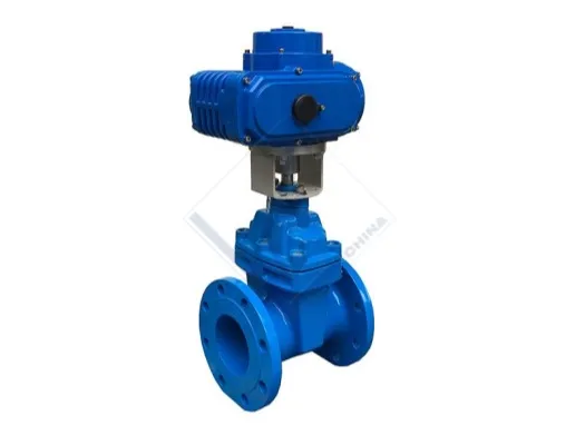
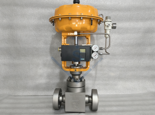
The product name specifies an Electric Actuator Cast Steel Gate Valve. Most industrial applications use electric actuators for on‑off (open/close) service, but multi‑turn actuators can also provide modulating control.
Gate valves are not designed for throttling. The gate should be either fully open or fully closed. Partial opening exposes the seat and gate sealing surfaces to erosion from high‑velocity fluid flow, and the turbulent flow over a partially raised gate can cause vibration that shortens stem life. For any control application that requires a valve position between fully open and fully closed, specify a globe valve or control ball valve instead.
If modulating duty is unavoidable—typically in large‑bore water or low‑pressure gas systems where no better valve type fits the pipeline—the electric actuator must include a positioner that accepts a 4‑20mA control signal. The actuator then holds the gate at the commanded position via a feedback loop from a position sensor. This configuration costs significantly more than a simple on‑off switch and should only be specified after confirming that no quarter‑turn control valve fits the application.
When an electric actuator loses power, a manually operated gate valve requires someone to physically turn the handwheel. Most multi‑turn electric actuators include a handwheel with a clutch mechanism that disconnects the motor drive and engages a manual gear train. When power is restored, the clutch automatically re‑engages the motor.
For critical applications where valve positioning during power loss matters, an uninterruptible power supply (UPS) for the actuator control circuit is the correct solution, not hardware failsafe springs.
Cast steel gate valves dominate the industrial landscape for a reason: casting cost scales linearly with size, while forging in large diameters becomes prohibitively expensive. For nominal bore sizes DN50 and above (2 inches and larger), cast steel is the standard. For instrumentation and high‑pressure small‑bore lines (DN15‑DN40), forged steel offers better grain structure and defect density control at a small size penalty.
On availability, cast steel gate valves between PN16 and PN100 are stocked by industrial distributors globally. Forged steel equivalents in the same size range typically require a manufacturing lead time of 8‑12 weeks unless you are installing a specialty high‑pressure system.
TSV manufactures gate valves of both wedge and parallel designs, with Electric Actuator Cast Steel Gate Valve variants spanning pressure classes. The company applies ISO, API, ASME, ANSI, and BS standards across its product line. TSV can supply valves with cast steel bodies, multiple seat hardfacing options, and electric actuators configured for on‑off or modulating duty.
For projects that require traceability, TSV's documentation includes material certifications, seat hardfacing batch records, and actuator test reports. The company provides technical support for torque selection and actuator sizing and can perform witness testing at the factory before shipment.
Before a full shipment of electric gate valves arrives on site, a pre‑order validation should confirm at least the following three points using a single sample.
Request the factory seat test report. For a cast steel gate valves specified for zero leakage, the test medium (often nitrogen or water) and the test pressure must match your system's differential pressure requirement.
A simple dry bench test of the actuator turning the stem at no‑load pressure tells you nothing. The correct test seats the valve, applies the maximum differential pressure the system will see, then measures breakaway torque while opening. This torque figure should be well below the actuator's continuous rating but not so low that the valve opened during the test with zero seat lift.
If your application reaches 550°C, ask for a witness test where the valve is heated to operating temperature before switch verification. Limit switch drift with temperature is a known issue on valve assemblies; the switch's trip point can shift by as much as 5‑10% of stroke between cold and hot conditions.
The range of cast steel gate valves with electric actuators covers PN1.6 to PN16.0 and temperatures from ‑29°C to 550°C. The correct valve for your system depends on three numbers: operating temperature, differential pressure, and required cycle count.
If your process stays below 200°C with clean water or HVAC media, a soft‑seated parallel gate valve with a small electric actuator at the low end of the pressure range will serve you well. If your process involves superheated steam at 500°C or hydrocarbon service with coking concerns, you need a wedge gate valve, a metal‑hardfaced seat, and an actuator sized for breakaway torque with 25‑50% safety margin.
A valve that fails in service costs more than the actuator price difference.
Related News


E-mail: info@tsv-valve.com
Telephone: +86-13695850057
Whatsapp: +86-13695850057
Address: TianSheng Industrial Park,Dong'ou Industrial Zone,Oubei Town,Wenzhou City,Zhejiang Province,China